This project is a simple bidirectional LED chaser built entirely with transistors and discrete components.
Two switches allow you to move the illuminated LED to the right or left.
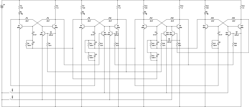
 How does it work ?
The circuit consists of four bistable multivibrator stages, with each stage controlling one LED.
A bistable multivibrator has two stable states. It can remain in either state until an external pulse causes it to switch to the other state.
The four bistable stages are interconnected so that the state of one stage affects the neighbouring stages.
When the right switch is closed, the next bistable to the right changes state.
At the same time, a pulse is fed back to the previous stage, causing that bistable to change state as well.
As a result, the LED that was previously on turns off, while the next LED turns on.
The same principle is applied when the left switch is closed.
This project is a good demonstration of how transistors can be used to create memory and logic functions without integrated circuits.
Electronics component Fun Kit (with breadboard & power supply module)
General purpose transistors - BC547 (NPN) & BC557 (PNP) pack
Disclosure: As an Amazon Associate, I earn from qualifying purchases. When you click these links to make a purchase, it helps support this website at no absolute extra cost to you.
 INDEX
